Internet Protocol version 4 (IPv4) is the fourth
revision in the development of the Internet Protocol (IP) and the first version of the
protocol to be widely deployed. Together with IPv6, it is at
the core of standards-based internetworking methods of the Internet.
IPv4 is still by far the most widely deployed Internet Layer protocol (As of 2011[update],
IPv6 deployment is still in its infancy).
IPv4 is described in IETF publication RFC 791
(September 1981), replacing an earlier definition (RFC 760,
January 1980).
IPv4 is a connectionless protocol for use on packet-switched Link Layer networks (e.g., Ethernet).
It operates on a best effort delivery model, in that it does not
guarantee delivery, nor does it assure proper sequencing or avoidance of
duplicate delivery. These aspects, including data integrity, are
addressed by an upper layer transport protocol , such as the Transmission Control Protocol
(TCP).
[edit] Addressing
IPv4 uses 32-
bit
(four-
byte)
addresses, which limits the
address
space to
4294967296
(2
32) addresses. However, some address blocks are reserved
for special purposes such as
private networks (~18 million addresses) and
multicast
addresses (~270 million addresses). This reduces the number of
addresses that may be allocated for routing on the public Internet. As
addresses are assigned to end users, an
IPv4 address shortage has been developing.
Network addressing changes by
classful network design,
Classless Inter-Domain Routing,
and
network address translation
(NAT) have contributed to delay significantly the inevitable exhaustion
which occurred on February 3, 2011 when IANA allocated the last five
blocks to the five
regional
Internet registries (RIRs).
This limitation stimulated the development of
IPv6 in the
1990s, which has been in commercial deployment since 2006.
[edit] Address representations
IPv4 addresses may be written in any notation expressing a 32-bit
integer value, but for human convenience, they are most often written in
dot-decimal notation, which consists of
four octets of the address expressed individually in
decimal
and separated by periods.
The following table shows several representation formats:
| Notation |
Value |
Conversion from dot-decimal |
| Dot-decimal notation |
192.0.2.235 |
N/A |
| Dotted Hexadecimal[1] |
0xC0.0x00.0x02.0xEB |
Each octet is individually converted to hexadecimal form |
| Dotted Octal[1] |
0300.0000.0002.0353 |
Each octet is individually converted into octal |
| Hexadecimal |
0xC00002EB |
Concatenation of the octets from the dotted hexadecimal |
| Decimal |
3221226219 |
The 32-bit number expressed in decimal |
| Octal |
030000001353 |
The 32-bit number expressed in octal |
[edit] Allocation
Originally, an IP address was divided into two parts, the network
identifier represented in the most significant (highest order)
octet of the address and the host identifier using the
rest of the address. The latter was therefore also called the
rest
field. This enabled the creation of a maximum of 256 networks. This
was quickly found to be inadequate.
To overcome this limit, the high order octet of the addresses was
redefined to create a set of
classes of networks, in a system
which later became known as
classful networking. The system defined five classes, Class
A, B, C, D, and E. The Classes A, B, and C had different bit lengths
for the new network identification. The rest of an address was used as
previously to identify a host within a network, which meant that each
network class had a different capacity to address hosts. Class D was
allocated for
multicast addressing and Class E was reserved for
future applications.
Starting around 1985, methods were devised to allow IP networks to be
subdivided. The concept of the
variable-length subnet mask (
VLSM) was introduced which allowed flexible
subdivision into varying network sizes.
[2][3]
Around 1993, this system of classes was officially replaced with
Classless Inter-Domain Routing
(CIDR), and the class-based scheme was dubbed
classful, by
contrast.
CIDR was designed to permit repartitioning of any address space so
that smaller or larger blocks of addresses could be allocated to users.
The hierarchical structure created by CIDR is managed by the
Internet Assigned Numbers
Authority (IANA) and the
regional Internet
registries (RIRs). Each RIR maintains a publicly-searchable
WHOIS database that provides information about
IP address assignments.
[edit] Special-use addresses
[edit] Private networks
Of the approximately four billion addresses allowed in IPv4, three
ranges of address are reserved for use in
private networks. These ranges are not routable outside of
private networks and private machines cannot directly communicate with
public networks. They can, however, do so through
network address translation.
The following are the three ranges reserved for private networks (
RFC 1918):
| Name |
Address range |
Number of addresses |
Classful description |
Largest CIDR block |
| 24-bit block |
10.0.0.0–10.255.255.255 |
16777216 |
Single Class A |
10.0.0.0/8 |
| 20-bit block |
172.16.0.0–172.31.255.255 |
1048576 |
Contiguous range of 16 Class B blocks |
172.16.0.0/12 |
| 16-bit block |
192.168.0.0–192.168.255.255 |
65536 |
Contiguous range of 256 Class C blocks |
192.168.0.0/16 |
[edit] Virtual private
networks
Packets with a private destination address are ignored by all public
routers. Therefore, it is not possible to communicate directly between
two private networks (e.g., two branch offices) via the public Internet.
This requires the use of
IP
tunnels or a
virtual private network (VPN).
VPNs establish tunneling connections across the public network such
that the endpoints of the tunnel function as routers for packets from
the private network. In this routing function the host encapsulates
packets in a protocol layer with packet headers acceptable in the public
network so that they may be delivered to the opposing tunnel end point
where the additional protocol layer is removed and the packet is
delivered locally to its intended destination.
Optionally, encapsulated packets may be encrypted to secure the data
while it travels over the public network.
[edit] Link-local addressing
RFC 5735 defines an
address block, 169.254.0.0/16, for the special use in link-local
addressing. These addresses are only valid on the link, such as a local
network segment or point-to-point connection, that a host is connected
to. These addresses are not routable and like private addresses cannot
be the source or destination of packets traversing the Internet.
Link-local addresses are primarily used for address autoconfiguration (
Zeroconf) when a host cannot obtain an IP
address from a DHCP server or other internal configuration methods.
When the address block was reserved, no standards existed for
mechanisms of address autoconfiguration. Filling the void,
Microsoft
created an implementation called Automatic Private IP Addressing
(APIPA). Due to Microsoft's market power, APIPA has been deployed on
millions of machines and has, thus, become a
de facto
standard in the industry. Many years later, the
IETF defined a formal standard for this
functionality,
RFC 3927, entitled
Dynamic
Configuration of IPv4 Link-Local Addresses.
[edit] Localhost
The address range 127.0.0.0–127.255.255.255 (127.0.0.0/8 in
CIDR
notation) is reserved for
localhost
communication. Addresses within this range should never appear outside a
host computer and packets sent to this address are returned as incoming
packets on the same virtual network device (known as
loopback).
[edit] Addresses ending
in 0 or 255
Networks with subnet masks of at least 24 bits, i.e. Class C networks
in classful networking, and networks with CIDR prefixes /24 to /32
(255.255.255.0–255.255.255.255) may not have an address ending in 0 or
255.
Classful addressing prescribed only three possible subnet masks:
Class A, 255.0.0.0 or /8; Class B, 255.255.0.0 or /16; and Class C,
255.255.255.0 or /24. For example, in the subnet
192.168.5.0/255.255.255.0 (192.168.5.0/24) the identifier 192.168.5.0
commonly is used to refer to the entire subnet. To avoid ambiguity in
representation, the address ending in the octet
0 is reserved.
A
broadcast address is an address that
allows information to be sent to all interfaces in a given subnet,
rather than a specific machine. Generally, the broadcast address is
found by obtaining the bit complement of the subnet mask and performing a
bitwise OR operation with the network identifier. In other words, the
broadcast address is the last address in the address range of the
subnet. For example, the broadcast address for the network 192.168.5.0
is 192.168.5.255. For networks of size /24 or larger, the broadcast
address always ends in 255.
However, this does not mean that every address ending in 0 or 255
cannot be used as a host address. For example, in the case of a /16
subnet 192.168.0.0/255.255.0.0, equivalent to the address range
192.168.0.0–192.168.255.255, the broadcast address is 192.168.255.255.
However, one may assign 192.168.1.255, 192.168.2.255, etc. 192.168.0.0
is the network identifier which should not be assigned to an interface,
[4]
but 192.168.1.0, 192.168.2.0, etc. may be assigned.
In the past, conflict between network addresses and broadcast
addresses arose because some software used non-standard broadcast
addresses with zeros instead of ones.
[5]
In networks smaller than /24, broadcast addresses do not necessarily
end with 255. For example, a CIDR subnet 203.0.113.16/28 has the
broadcast address 203.0.113.31.
[edit] Address resolution
Hosts on the
Internet are usually known by names, e.g.,
www.example.com, not primarily by their IP address, which is used for
routing and network interface identification. The use of domain names
requires translating, called
resolving, them to addresses and
vice versa. This is analogous to looking up a phone number in a phone
book using the recipient's name.
The translation between addresses and domain names is performed by
the
Domain Name System (DNS), a hierarchical,
distributed naming system which allows for subdelegation of name spaces
to other DNS servers. DNS is often described in analogy to the
telephone system directory information systems in which subscriber names
are translated to telephone numbers.
[edit] Address space
exhaustion
Since the 1980s it was apparent that the pool of available IPv4
addresses was depleted at a rate that was not initially anticipated in
the original design of the network address system.
[6]
The apparent threat of exhaustion was the motivation for remedial
technologies, such as the introduction of
classful networks, the creation of
Classless Inter-Domain Routing
(CIDR) methods, and
network address translation
(NAT), and finally for the redesign of the Internet Protocol, based on a
larger address format (
IPv6).
Several market forces have driven the acceleration of IPv4 address
exhaustion:
A variety of technologies introduced during the growth of the
Internet have been applied to mitigate IPv4 address exhaustion and its
effects, such as:
The primary address pool of the Internet, maintained by IANA, was
exhausted on 3 February 2011 when the last 5 blocks were allocated to
the 5 RIRs.
[7][8]
APNIC was the first
RIR to exhaust its regional pool on 15 April 2011, except for a small
amount of address space reserved for the transition to IPv6, which will
be allocated under a much more restricted policy.
[9]
The accepted and standardized solution is the migration to
Internet Protocol
Version 6. The address size was increased in IPv6 to 128 bits,
providing a vastly increased address space that also allows improved
route aggregation across the Internet and offers large subnetwork
allocations of a minimum of 2
64 host addresses to end-users.
Migration to IPv6 is in progress but completion is expected to take
considerable time.
[edit] Packet structure
An IP packet consists of a header section and a data section.
The IPv4 packet header consists of 14 fields, of which 13 are
required. The 14th field is optional (red background in table) and aptly
named: options. The fields in the header are packed with the most
significant byte first (
big
endian), and for the diagram and discussion, the most significant
bits are considered to come first (
MSB 0 bit numbering). The most significant bit
is numbered 0, so the version field is actually found in the four most
significant bits of the first byte, for example.
- Version
- The first header field in an IP packet
is the four-bit version field. For IPv4, this has a value of 4 (hence
the name IPv4).
- Internet Header Length (IHL)
- The second field (4 bits) is the Internet Header Length (IHL)
telling the number of 32-bit words in the header. Since an IPv4
header may contain a variable number of options, this field specifies
the size of the header (this also coincides with the offset to the
data). The minimum value for this field is 5 (RFC 791),
which is a length of 5×32 = 160 bits = 20 bytes. Being a 4-bit value,
the maximum length is 15 words (15×32 bits) or 480 bits = 60 bytes.
- Differentiated Services Code Point (DSCP)
- Originally defined as the Type of Service field, this field is
now defined by RFC 2474 for Differentiated services (DiffServ).
New technologies are emerging that require real-time data streaming and
therefore make use of the DSCP field. An example is Voice
over IP (VoIP) that is used for interactive data voice exchange.
- Explicit Congestion Notification (ECN)
- Defined in RFC 3168 and allows
end-to-end notification of network congestion without dropping packets. ECN is an
optional feature that is only used when both endpoints support it and
are willing to use it. It is only effective when supported by the
underlying network.
- Total Length
- This 16-bit field defines the entire datagram size, including header
and data, in bytes. The minimum-length datagram is 20 bytes (20-byte
header + 0 bytes data) and the maximum is 65,535 bytes — the maximum
value of a 16-bit word. The maximum size datagram that any host is
required to be able to handle is 576 bytes, but most modern hosts handle
much larger packets. Sometimes subnetworks
impose further restrictions on the size, in which case datagrams must
be fragmented. Fragmentation is handled in either the host or packet
switch in IPv4.
- Identification
- This field is an identification field and is primarily used for
uniquely identifying fragments of an original IP datagram. Some
experimental work has suggested using the ID field for other purposes,
such as for adding packet-tracing information to datagrams in order to
help trace back datagrams with spoofed source addresses.[10]
- Flags
- A three-bit field follows and is used to control or identify
fragments. They are (in order, from high order to low order):
- bit 0: Reserved; must be zero.[note
1]
- bit 1: Don't Fragment (DF)
- bit 2: More Fragments (MF)
- If the DF flag is set and fragmentation is required to route the
packet then the packet is dropped. This can be used when sending packets
to a host that does not have sufficient resources to handle
fragmentation. It can also be used for Path MTU Discovery, either automatically by the host IP
software, or manually using diagnostic tools such as ping or traceroute.
- For unfragmented packets, the MF flag is cleared. For fragmented
packets, all fragments except the last have the MF flag set. The last
fragment has a non-zero Fragment Offset field, differentiating it from
an unfragmented packet.
- Fragment Offset
- The fragment offset field, measured in units of eight-byte blocks,
is 13 bits long and specifies the offset of a particular fragment
relative to the beginning of the original unfragmented IP datagram. The
first fragment has an offset of zero. This allows a maximum offset of (213
– 1) × 8 = 65,528 bytes which would exceed the maximum IP packet length
of 65,535 bytes with the header length included (65,528 + 20 = 65,548
bytes).
- Time To Live (TTL)
- An eight-bit time to live field helps prevent datagrams from
persisting (e.g. going in circles) on an internet. This field limits a
datagram's lifetime. It is specified in seconds, but time intervals less
than 1 second are rounded up to 1. In latencies typical in practice, it
has come to be a hop count field. Each router that a datagram crosses decrements the TTL
field by one. When the TTL field hits zero, the packet is no longer
forwarded by a packet switch and is discarded. Typically, an ICMP Time Exceeded message is sent back to the sender to
inform it that the packet has been discarded. The reception of these
ICMP messages is at the heart of how traceroute
works.
- Protocol
- This field defines the protocol used in the data portion of the IP
datagram. The Internet Assigned Numbers
Authority maintains a list of IP protocol numbers
which was originally defined in RFC 790.
- Header Checksum
-
The 16-bit checksum field is used for error-checking of the
header. At each hop, the checksum of the header must be compared to the
value of this field. If a header checksum is found to be mismatched,
then the packet is discarded. Errors in the data field must be handled
by the encapsulated protocol and both UDP and TCP have checksum fields.
- As the TTL field is decremented on each hop, a new checksum must be
computed each time. The method used to compute the checksum is defined
by RFC 1071:
- The checksum field is the 16-bit one's complement of the one's complement sum of all
16-bit words in the header. For purposes of computing the checksum, the
value of the checksum field is zero.
- For example, use Hex 4500003044224000800600008c7c19acae241e2b (20
bytes IP header):
- 4500 + 0030 + 4422 + 4000 + 8006 + 0000 + 8c7c + 19ac + ae24 + 1e2b =
2BBCF
- 2 + BBCF = BBD1 = 1011101111010001, the 1'S of sum =
0100010000101110 = 442E
- To validate a header's checksum the same algorithm may be used - the
checksum of a header which contains a correct checksum field is a word
containing all zeros (value 0):
- 2BBCF + 442E = 2FFFD. 2 + FFFD = FFFF. the 1'S of FFFF = 0.
- Source address
- An IPv4 address indicating the
sender of the packet. Note that this address may be changed in transit
by a network address translation
device.
- Destination address
- An IPv4 address indicating the
receiver of the packet. As with the Source address, this may be changed
in transit by a network address translation
device.
- Options
- Additional header fields may follow the destination address field,
but these are not often used. Note that the value in the IHL field must
include enough extra 32-bit words to hold all the options (plus any
padding needed to ensure that the header contains an integral number of
32-bit words). The list of options may be terminated with an EOL (End of
Options List, 0x00) option; this is only necessary if the end of the
options would not otherwise coincide with the end of the header. The
possible options that can be put in the header are as follows:
| Field |
Size (bits) |
Description |
| Copied |
1 |
Set to 1 if the options need to be copied into all fragments of a
fragmented packet. |
| Option Class |
2 |
A general options category. 0 is for "control" options, and 2
is for "debugging and measurement". 1, and 3 are reserved. |
| Option Number |
5 |
Specifies an option. |
| Option Length |
8 |
Indicates the size of the entire option (including this field). This
field may not exist for simple options. |
| Option Data |
Variable |
Option-specific data. This field may not exist for simple options. |
- Note: If the header length is greater than 5, i.e. it is from 6 to
15, it means that the options field is present and must be considered.
- Note: Copied, Option Class, and Option Number are sometimes referred
to as a single eight-bit field - the Option Type.
- The use of the LSRR and SSRR
options (Loose and Strict Source and Record Route) is discouraged
because they create security concerns; many routers block packets
containing these options.[citation needed]
The data portion of the packet is not included in the packet
checksum. Its contents are interpreted based on the value of the
Protocol header field.
In a typical IP implementation, standard protocols such as TCP and
UDP are implemented in the
OS kernel for performance reasons. Other protocols
such as ICMP may be partially implemented by the kernel, or implemented
purely in user software. Protocols not implemented in-kernel, and not
exposed by standard APIs such as
BSD sockets, are typically implemented using a '
raw
socket' API.
Some of the common protocols for the data portion are listed below:
See
List of IP protocol numbers for a
complete list.
[edit] Fragmentation and
reassembly
The Internet Protocol is the facility in the Internet architecture
that enables different networks to exchange traffic and route traffic
across one another. The design accommodates networks of diverse physical
nature; it is independent of the underlying transmission technology
used in the Link Layer. Link Layer networks of different hardware design
usually vary not only in transmission speed, but also in the structure
and size of valid framing methods, characterized by the
maximum transmission unit (MTU)
parameter. To fulfill the role of IP to traverse networks, it was
necessary to implement a mechanism to automatically adjust the size of
transmission units to adapt to the underlying technology. This
introduced the need for
fragmentation
of IP datagrams. In IPv4, this function was placed at the
Internet Layer, and is performed in IPv4
routers, which thus only require this layer as highest one implemented
in their design.
In contrast, the next generation of the Internet Protocol, namely
IPv6, does not
require routers to perform fragmentation; instead, hosts must determine
the path maximum transmission unit in advance of transmission and send
conforming datagrams.
[edit] Fragmentation
When a device receives an IP packet it examines the destination
address and determines the outgoing interface to use. This interface has
an associated MTU that dictates the maximum data size for its payload.
If the data size is bigger than the MTU then the device must fragment
the data.
The device then segments the data into segments where each segment is
less-than-or-equal-to the MTU less the IP header size (20 bytes
minimum; 60 bytes maximum). Each segment is then put into its own IP
packet with the following changes:
- The total length field is adjusted to the segment size
- The more fragments (MF) flag is set for all segments except
the last one, which is set to 0
- The fragment offset field is set accordingly based on the
offset of the segment in the original data payload. This is measured in
units of eight-byte blocks.
- The header checksum field is recomputed.
For example, for an IP header of length 20 bytes and an Ethernet MTU
of 1,500 bytes the fragment offsets would be: 0, (1480/8) = 185,
(2960/8) = 370, (4440/8) = 555, (5920/8) = 740, etc.
By some chance if a packet changes link layer protocols or the MTU
reduces then these fragments would be fragmented again.
For example, if a 4,500-byte data payload is inserted into an IP
packet with no options (thus total length is 4,520 bytes) and is
transmitted over a link with an MTU of 2,500 bytes then it will be
broken up into two fragments:
| # |
Total length |
More fragments (MF)
flag set? |
Fragment offset |
| Header |
Data |
| 1 |
2500 |
Yes |
0 |
| 20 |
2480 |
| 2 |
2040 |
No |
310 |
| 20 |
2020 |
Now, let's say the MTU drops to 1,500 bytes. Each fragment will
individually be split up into two more fragments each:
| # |
Total length |
More fragments (MF)
flag set? |
Fragment offset |
| Header |
Data |
| 1 |
1500 |
Yes |
0 |
| 20 |
1480 |
| 2 |
1020 |
Yes |
185 |
| 20 |
1000 |
| 3 |
1500 |
Yes |
310 |
| 20 |
1480 |
| 4 |
560 |
No |
495 |
| 20 |
540 |
Indeed, the amount of data has been preserved — 1480 + 1000 + 1480 +
540 = 4500 — and the last fragment offset (495) * 8 (bytes) plus data —
3960 + 540 = 4500 — is also the total length.
Note that fragments 3 & 4 were derived from the original fragment
2. When a device must fragment the last fragment then it must set the
flag for all but the last fragment it creates (fragment 4 in this case).
Last fragment would be set to 0 value.
[edit] Reassembly
When a receiver detects an IP packet where either of the following is
true:
- "more fragments" flag set
- "fragment offset" field is non-zero
then the receiver knows the packet is a fragment. The receiver then
stores the data with the identification field, fragment offset, and the
more fragments flag. When the receiver receives a fragment with the more
fragments flag set to 0 then it knows the length of the original data
payload since the fragment offset multiplied by 8 (bytes) plus the data
length is equivalent to the original data payload size.
Using the example above, when the receiver receives fragment 4 the
fragment offset (495 or 3960 bytes) and the data length (540 bytes)
added together yield 4500 — the original data length.
Once it has all the fragments then it can reassemble the data in
proper order (by using the fragment offsets) and pass it up the stack
for further processing.
[edit] Assistive protocols
The Internet Protocol is the protocol that defines and enables
internetworking at the
Internet Layer and thus forms the
Internet. It uses a logical addressing system. IP addresses are not tied
in any permanent manner to hardware identifications and, indeed, a
network interface can have multiple IP addresses. Hosts and routers need
additional mechanisms to identify the relationship between device
interfaces and IP addresses, in order to properly deliver an IP packet
to the destination host on a link. The
Address Resolution Protocol
(ARP) performs this IP address to hardware address (
MAC
address) translation for IPv4. In addition, the reverse correlation
is often necessary. For example, when an IP host is booted or connected
to a network it needs to determine its IP address, unless an address is
preconfigured by an administrator. Protocols for such inverse
correlations exist in the
Internet Protocol
Suite. Currently used methods are
Dynamic Host Configuration
Protocol (DHCP),
Bootstrap Protocol (BOOTP) and, infrequently,
reverse ARP.
[edit] See also
- ^ As an April Fools' joke, proposed for use in RFC 3514 as the "Evil bit".
[edit] References
[edit] External links
Address exhaustion:
Protokol Internet (
Inggris Internet Protocol disingkat IP) adalah
protokol lapisan jaringan (
network layer dalam OSI
Reference Model) atau protokol lapisan
internetwork (
internetwork layer dalam DARPA
Reference Model) yang digunakan oleh protokol
TCP/IP untuk melakukan pengalamatan dan
routing
paket data antar
host-host di
jaringan komputer berbasis
TCP/IP. Versi IP yang banyak digunakan adalah IP
versi 4 (IPv4) yang didefinisikan pada
RFC 791
dan dipublikasikan pada tahun
1981, tetapi
akan digantikan oleh
IP versi 6 pada beberapa waktu yang akan datang.
Protokol IP merupakan salah satu protokol kunci di dalam kumpulan
protokol TCP/IP. Sebuah paket IP akan membawa data aktual yang
dikirimkan melalui jaringan dari satu titik ke titik lainnya. Metode
yang digunakannya adalah
connectionless yang berarti ia tidak
perlu membuat dan memelihara sebuah sesi koneksi. Selain itu, protokol
ini juga tidak menjamin penyampaian data, tapi hal ini diserahkan kepada
protokol pada lapisan yang lebih tinggi (
lapisan transport dalam OSI
Reference Model atau
lapisan antar host dalam DARPA
Reference Model), yakni protokol
Transmission Control Protocol
(TCP).
[sunting]
Layanan
yang ditawarkan oleh Protokol IP
- IP menawarkan layanan sebagai protokol antar jaringan
(inter-network), karena itulah IP juga sering disebut sebagai protokol
yang bersifat routable. Header IP mengandung informasi yang dibutuhkan
untuk menentukan rute paket, yang mencakup alamat
IP sumber (source IP address) dan alamat
IP tujuan (destination IP address). Anatomi alamat IP terbagi
menjadi dua bagian, yakni alamat jaringan (network address) dan
alamat node (node address/host address). Penyampaian paket
antar jaringan (umumnya disebut sebagai proses routing),
dimungkinkan karena adanya alamat jaringan tujuan dalam alamat IP.
Selain itu, IP juga mengizinkan pembuatan sebuah jaringan yang cukup
besar, yang disebut sebagai IP internetwork, yang terdiri atas dua atau
lebih jaringan yang dihubungkan dengan menggunakan router berbasis IP.
- IP mendukung banyak protokol klien, karena memang IP merupakan
"kurir" pembawa data yang dikirimkan oleh protokol-protokol lapisan yang
lebih tinggi dibandingkan dengannya. Protokol IP dapat membawa beberapa
protokol lapisan tinggi yang berbeda-beda, tapi setiap paket IP hanya
dapat mengandung data dari satu buah protokol dari banyak protokol
tersebut dalam satu waktu. Karena setiap paket dapat membawa satu buah
paket dari beberapa paket data, maka harus ada cara yang digunakan untuk
mengidikasikan protokol lapisan tinggi dari paket data yang dikirimkan
sehingga dapat diteruskan kepada protokol lapisan tinggi yang sesuai
pada sisi penerima. Mengingat klien dan server selalu menggunakan
protokol yang sama untuk sebuah data yang saling dipertukarkan, maka
setiap paket tidak harus mengindikasikan sumber dan tujuan yang
terpisah. Contoh dari protokol-protokol lapisan yang lebih tinggi
dibandingkan IP adalah Internet Control Management Protocol (ICMP),
Internet Group Management Protocol (IGMP), User Datagram Protocol (UDP),
dan Transmission Control Protocol (TCP).
- IP mengirimkan data dalam bentuk datagram, karena memang IP hanya
menyediakan layanan pengiriman data secara connectionless serta tidak
andal (unreliable) kepada protokol-protokol yang berada lebih tinggi
dibandingkan dengan protokol IP. Pengirimkan connectionless, berarti
tidak perlu ada negosiasi koneksi (handshaking) sebelum
mengirimkan data dan tidak ada koneksi yang harus dibuat atau dipelihara
dalam lapisan ini. Unreliable, berarti IP akan mengirimkan paket tanpa
proses pengurutan dan tanpa acknowledgment ketika
pihak yang dituju telah dapat diraih. IP hanya akan melakukan pengiriman
sekali kirim saja untuk menyampaikan paket-paket kepada hop selanjutnya
atau tujuan akhir (teknik seperti ini disebut sebagai "best effort
delivery"). Keandalan data bukan merupakan tugas dari protokol IP, tapi
merupakan protokol yang berada pada lapisan yang lebih tinggi, seperti
halnya protokol TCP.
- Bersifat independen dari lapisan antarmuka jaringan (lapisan pertama
dalam DARPA Reference Model), karena memang IP didesain agar mendukung
banyak komputer dan antarmuka jaringan. IP bersifat independen terhadap
atribut lapisan fisik,
seperti halnya pengabelan, pensinyalan, dan bit rate. Selain itu, IP
juga bersifat independen terhadap atribut lapisan data link seperti
halnya mekanisme Media access control (MAC),
pengalamatan MAC, serta ukuran frame terbesar. IP menggunakan skema
pengalamatannya sendiri, yang disebut sebagai "IP
address", yang merupakan bilangan 32-bit dan independen terhadap
skema pengalamatan yang digunakan dalam lapisan antarmuka jaringan.
- Untuk mendukung ukuran frame terbesar yang dimiliki oleh teknologi
lapisan antarmuka jaringan yang berbeda-beda, IP dapat melakukan
pemecahan terhadap paket data ke dalam beberapa fragmen sebelum
diletakkan di atas sebuah saluran jaringan. Paket data tersebut akan
dipecah ke dalam fragmen-fragmen yang memiliki ukuran maximum
transmission unit (MTU) yang lebih rendah dibandingkan dengan ukuran
datagram IP. Proses ini dinamakan dengan fragmentasi ([[Fragmentasi
paket jaringan|fragmentation). Router atau host yang mengirimkan
data akan memecah data yang hendak ditransmisikan, dan proses
fragmentasi dapat berlangsung beberapa kali. Selanjutnya host yang
dituju akan menyatukan kembali fragmen-fragmen tersebut menjadi paket
data utuh, seperti halnya sebelum dipecah.
- Dapat diperluas dengan menggunakan fitur IP Options dalam header
IP. Fitur yang dapat ditambahkan contohnya adalah kemampuan untuk
menentukan jalur yang harus diikuti oleh datagram IP melalui sebuah internetwork
IP.

Format datagram Protokol IP
Paket-paket data dalam protokol IP dikirimkan dalam bentuk datagram.
Sebuah datagram IP terdiri atas header IP dan muatan IP (payload),
sebagai berikut:
- Header IP: Ukuran header IP bervariasi, yakni berukuran 20 hingga 60
byte, dalam penambahan 4-byte. Header IP menyediakan dukungan untuk
memetakan jaringan (routing), identifikasi muatan IP, ukuran header IP
dan datagram IP, dukungan fragmentasi, dan juga IP Options.
- Muatan IP: Ukuran muatan IP juga bervariasi, yang berkisar dari 8
byte hingga 65515 byte.
Sebelum dikirimkan di dalam saluran jaringan, datagram IP akan
"dibungkus" dengan header protokol lapisan antarmuka jaringan dan
trailer-nya, untuk membuat sebuah
frame jaringan.

Format Header Protokol IP
Header IP terdiri atas beberapa field sebagai berikut:
| Field |
Panjang |
Keterangan |
| Version |
4 bit |
Digunakan untuk mengindikasikan versi dari header IP yang
digunakan. Karena memiliki panjang 4 bit, maka terdapat 24=16
buah jenis nilai yang berbeda-beda, yang berkisar antara 0 hingga 15.
Meskipun begitu hanya ada dua nilai yang bisa digunakan, yakni 4 dan 6,
mengingat versi IP standar yang digunakan saat ini dalam jaringan dan
Internet adalah versi 4 dan 6 merupakan singkatan dari versi selanjutnya
(IPv6).
Lihat situs web IANA
untuk informasi mengenai field ini lebih lanjut. |
| Header length |
4 bit |
Digunakan untuk mengindikasikan ukuran header IP. Karena
memiliki panjang 4 bit, maka terdapat 24=16 buah jenis nilai
yang berbeda-beda. Field header length ini mengindikasikan
bilangan double-word 32-bit (blok 4-byte) di dalam header IP.
Ukuran terkecilnya adalah 5 (0x05), yang menunjukkan ukuran terkecil
dari header IP yakni 20 byte. Dengan jumlah maksimum dari IP
Options, ukuran header IP maksimum adalah 60 byte,
yang diindikasikan dengan nilai 15 (0x0F). |
| Type of Service (TOS) |
8 bit |
Field ini digunakan untuk menentukan kualitas transmisi dari
sebuah datagram IP. Ada dua jenis TOS yang didefinisikan, yakni pada RFC 791 dan RFC 2474. Hal ini akan
dibahas pada seksi berikutnya. |
| Total Length |
16 bit |
Merupakan panjang total dari datagram IP, yang mencakup
header IP dan muatannya. Dengan menggunakan angka 16 bit, nilai maksimum
yang dapat ditampung adalah 65535 byte. Untuk datagram IP yang memiliki
ukuran maksimum, field ini memiliki nilai yang sama dengan nilai
maximum
transmission unit yang dimiliki oleh teknologi protokol lapisan
antarmuka jaringan. |
| Identifier |
16 bit |
Digunakan untuk mengidentifikasikan sebuah paket IP tertentu yang
dikirimkan antara node sumber dan node tujuan. Host pengirim akan
mengeset nilai dari field ini, dan field ini akan
bertambah nilainya untuk datagram IP selanjutnya. Field ini
digunakan untuk mengenali fragmen-fragmen sebuah datagram IP. |
| Flag |
3 bit |
Berisi dua buah flag yang berisi apakah sebuah datagram IP
mengalami fragmentasi atau tidak. Meski berisi tiga bit, ada dua
jenis nilai yang mungkin, yakni apakah hendak memecah datagram IP
ke dalam beberapa fragmen atau tidak. |
| Fragment Offset |
13 bit |
Digunakan untuk mengidentifikasikan ofset di mana fragmen
yang bersangkutan dimulai, dihitung dari permulaan muatan IP yang belum
dipecah. |
| Time-to-Live (TTL) |
8 bit |
Digunakan untuk mengidentifikasikan berapa banyak saluran jaringan
di mana sebuah datagram IP dapat berjalan-jalan sebelum sebuah router
mengabaikan datagram tersebut. Field ini pada awalnya
ditujukan sebagai penghitung waktu, untuk mengidentifikasikan berapa
lama (dalam detik) sebuah datagram IP boleh terdapat di dalam
jaringan. Adalah router IP yang memantau nilai ini, yang akan
berkurang setiap kali hinggap dalam router. |
| Protocol |
8 bit |
Digunakan untuk mengidentifikasikan jenis protokol lapisan yang
lebih tinggi yang dikandung oleh muatan IP. Field ini merupakan
tanda eksplisit untuk protokol klien. Terdapat beberapa nilai dari field
ini, seperti halnya nilai 1 (0x01) untuk ICMP, 6 (0x06) untuk TCP, dan
17 (0x11) untuk UDP (selengkapnya lihat di bawah). Field ini
bertindak sebagai penanda multipleks (multiplex identifier),
sehingga muatan IP pun dapat diteruskan ke protokol lapisan yang lebih
tinggi saat diterima oleh node yang dituju. |
| Header Checksum |
16 bit |
Field ini berguna hanya untuk melakukan pengecekan integritas
terhadap header IP, sementara muatan IP sendiri tidak dimasukkan
ke dalamnya, sehingga muatan IP harus memiliki checksum mereka
sendiri untuk melakukan pengecekan integritas terhadap muatan IP. Host
pengirim akan melakukan pengecekan checksum terhadap datagram
IP yang dikirimkan. Setiap router yang berada di dalam jalur
transmisi antara sumber dan tujuan akan melakukan verifikasi terhadap field
ini sebelum memproses paket. Jika verifikasi dianggap gagal, router
pun akan mengabaikan datagram IP tersebut.
Karena setiap router yang berada di dalam jalur transmisi antara
sumber dan tujuan akan mengurangi nilai TTL, maka header checksum
pun akan berubah setiap kali datagram tersebut hinggap di setiap
router yang dilewati.
Pada saat menghitung checksum terhadap semua field di
dalam header IP, nilai header checksum akan diset ke nilai
0. |
| Source IP Address |
32 bit |
Mengandung alamat IP dari sumber host yang mengirimkan
datagram IP tersebut, atau alamat IP dari Network Address
Translator (NAT). |
| Destination IP Address |
32 bit |
Mengandung alamat IP tujuan ke mana datagram IP
tersebut akan disampaikan, atau yang dapat berupa alamat dari host atau
NAT. |
| IP Options and Padding |
32 bit |
[place holder] |
[sunting] Type of Service
(ToS)
Field Type of Service (ToS) adalah sebuah
field
dalam
header IPv4 yang memiliki panjang 8 bit dan digunakan untuk
menandakan jenis
Quality of Service (QoS) yang digunakan oleh
datagram
yang bersangkutan untuk disampaikan ke
router-router
internetwork. ToS didefinisikan di dalam dua buah standar, yakni
RFC 791 dan
RFC 2474.
[place holder]
[place holder]
[sunting] Time-to-Live (TTL)
Berikut ini adalah nilai dari field Protocol
Untuk beberapa nilai lainnya, kunjungi alamat
situs web IANA.
Aplikasi jaringan
Windows yang berbasis
Windows
Sockets API (WinSock) dapat merujuk protokol berdasarkan namanya
saja. Nama-nama protokol kemudian akan diterjemahkan ke dalam nomor
protokol dengan menggunakan berkas yang disimpan di dalam
%systemroot%\System32\Drivers\Etc\Protocol.
[sunting] Fragmentasi Paket IP
Ketika sebuah host sumber atau router harus mentransmisikan sebuah
datagram IP dalam sebuah saluran jaringan di mana nilai Maximum
transmission unit (MTU) yang dimilikinya lebih kecil dibandingkan ukuran
datagram IP, datagram IP yang akan ditransmisikan tersebut harus
dipecah ke dalam beberapa fragmen. Proses ini disebut sebagai
Fragmentation (fragmentasi). Ketika fragmentasi terjadi, muatan IP akan
dibelah menjadi beberapa segmen, dan setiap segmen akan dikirimkan
dengan header IP-nya masing-masing.
Header IP mengandung informasi yang dibutuhkan untuk
menyatukan kembali muatan IP yang telah dipecah tersebut menjadi muatan
IP yang utuh pada saat datagram IP tersebut telah sampai pada
host
tujuan. Karena IP merupakan teknologi
datagram packet-switching
dan juga fragmen dapat sampai ke tujuan dalam kondisi tidak terurut,
fragmen-fragmen tersebut harus dikelompokkan (dengan menggunakan
field
Identification dalam
header IP), diurutkan (dengan
menggunakan
field Fragment Offset dalam
header IP),
dan diperjelas pembatasannya (dengan menggunakan
flag More
Fragment dalam
header IP).
Teknologi
virtual circuit packet-switching seperti halnya
X.25 dan
Asynchronous Transfer Mode (ATM)
hanya membutuhkan pembatasan fragmen/segmen. Sebagai contoh, dengan
ATM
Adaptation Layer 5, sebuah datagram IP akan dibelah menjadi
beberapa segmen berukuran 48
byte yang menjadi muatan setiap sel
ATM. ATM selanjutnya mengirimkan sel-sel ATM tersebut yang mengandung
datagram IP dan menggunakan bit ketiga dari
field Payload Type
di dalam
header ATM untuk mengindikasikan akhir aliran sel ATM
untuk sebuah datagram IP.
Ada tiga buah
field yang berguna untuk menunjukkan apakah
sebuah datagram IP harus difragmentasi atau tidak, yakni sebagai
berikut:
- Field identification:
Digunakan untuk mengelompokkan semua fragmen dari sebuah datagram IP
dalam sebuah kelompok. Host pengirim akan mengeset nilai field ini, dan
nilai ini tidak akan beruba selama proses fragmentasi berlangsung. Field
ini selalu diset (memiliki nilai) meskipun datagram IP tidak boleh
diset dengan menggunakan bit flag Dont Fragment (DF).
- Field Flag, yang memiliki dua buah nilai:
- Don't fragment (DF):
Flag ini akan diset ke nilai "0" untuk mengizinkan fragmentasi
dilakukan, atau nilai "1" untuk mencegah fragmentasi dilakukan terhadap
datagram IP. Dengan kata lain, fragmentasi akan terjadi jika flag DF ini
bernilai "0". Jika fragmentasi dibutuhkan untuk meneruskan datagram IP
(akibat ukuran datagram IP yang lebih besar dibandingkan dengan ukuran
maximum transmission unit (MTU)) dan flag DF ini diset ke nilai "1",
maka router akan mengirimkan pesan "ICMP Destination
Unreachable-Fragmentation Needed And DF Set" kepada host pengirim,
sebelum router tersebut akan mengabaikan datagram IP tersebut.
- More Fragments (MF):
Flag ini akan diset ke nilai "0" jika tidak ada fragmen lainnya yang
mengikuti fragmen yang bersangkutan (berarti tanda bahwa fragmen
tersebut merupakan fragmen terakhir), atau diset ke nilai "1" jika ada
tambahan fragmen yang mengikuti fragmen tersebut (berarti tanda bahwa
fragmen tersebut bukanlah fragmen terakhir).
- Field' Fragment Offset:
Field ini akan diset untuk mengindikasikan posisi fragmen yang
bersangkutan terhadap muatan IP yang belum difragmentasikan. Field
ini akan digunakan untuk mengurutkan kembali semua fragmen pada saat
proses penyatuan kembali menjadi sebuah datagram IP yang utuh di pihak
penerima. Ukurannya adalah 13 bit, sehingga mendukung nilai hingga 8191
saja.
Mengingat ukuran muatan IP terbesar adalah 65515 byte (216-20),
sedangkan ukuran field ini adalah 13 bit, maka field ini tidak dapat
digunakan untuk mengindikasikan byte offset. Karenanya setiap
nilai field fragment offset harus merepresentasikan nilai 3 bit.
Dengan demikian, field Fragment Offset pun dapat didefinisikan dalam
blok-blok berukuran 8 byte yang disebut sebagai Fragment block.
Selama fragmentasi dilakukan, muatan IP akan dipecah ke dalam
fragmen-fragmen dengan menggunakan batasan 8 byte dan nilai maksimum
fragment block (8 byte) diletakkan pada setiap fragmen. Field Fragment
Offset pun diset untuk mengindikasikan permulaan fragment block
untuk fragmen tersebut dibandingkan dengan muatan IP yang belum
difragmentasi.
Setiap fragmen yang difragmentasi oleh
router,
header IP akan disalin dan
beberapa field ini akan diubah selama fragmentasi oleh router:
- Header length: Bisa berubah atau tidak bergantung pada
keberadaan IP Options, dan juga apakah IP Options tersebut disalin ke
semua fragmen atau hanya fragmen pertama saja.
- Time-to-Live (TTL): selalu dikurangi 1.
- Total Length: Diubah untuk merefleksikan perubahan
pada header IP yang baru dan tentunya muatan IP yang baru.
- Flag More Fragment akan diset ke angka 1 untuk
fragmen pertama atau fragmen pertengahan, atau nilai 0 untuk fragmen
terakhir.
- Fragment Offset: Diset untuk mengindikasikan posisi
fragmen di dalam fragment block relatif terhadap muatan IP yang belum
difragmentasi.
- Header Checksum: dihitung ulang berdasarkan field yang
berubah di dalam header IP.
- Field "identification": tidak berubah untuk setiap fragmen.
[sunting] Contoh proses
fragmentasi
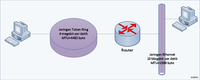
Contoh proses fragmentasi (gambar 1)
Sebagai sebuah contoh bagaimana proses fragmentasi berlangsung,
perhatikan skenairo berikut:
Sebuah node yang berada di dalam jaringan Token Ring mengirimkan sebuah
datagram IP yang dapat difragmentasikan dengan nilai field
Identification (dalam header IP) diset ke nilai 9999 ke sebuah node
dalam jaringan Ethernet, seperti terlukis dalam gambar. Anggaplah
jaringan Token Ring tersebut memiliki pengaturan sebagai berikut:
kepemilikan token selama 9 milidetik, kecepatan 4 megabit per detik, dan
tidak ada header routing Token Ring, serta MTU 4482 byte. Sementara
itu, jaringan Ethernet memiliki MTU 1500 byte, yang menggunakan skema
enkapsulasi frame
Ethernet II.
Sebelum fragmentasi terjadi, field-field dalam header IP untuk
datagram IP yang asli bernilai sebagai berikut:
| Field |
Nilai |
| Total Length |
4482 |
| Identification |
9999 |
| flag DF |
0 |
| flag MF |
0 |
| Fragment Offset |
0 |
Router yang menghubungkan dua jenis jaringan tersebut akan
menerima datagram IP dari komputer pengirim dalam jaringan Token Ring.
Router pun mengecek tabel routing yang ada di dalam dirinya dan
menentukan antarmuka mana yang hendak digunakan untuk meneruskan pesan
tersebut dan kemudian router mengetahui bahwa datagram IP yang
dikirimkan lebih besar daripada nilai MTU, mengingat jaringan yang
dituju merupakan jaringan Ethernet. Selanjutnya, router melihat flag DF
dalam header IP: jika diset ke angka 1, router akan mengabaikan datagram
yang bersangkutan dan mengirimkan pesan balasan "ICMP Destination
Unreachable-Fragmentation Needed And DF Set" kepada pengirim datagram
IP; dan karena memiliki nilai "0", router pun melakukan fragmentasi
terhadap muatan datagram IP tersebut, yakni sebesar 4462
byte
(dengan anggapan bahwa datagram tersebut tidak memiliki IP Options) ke
dalam empat buah fragmen, yang setiap fragmennya memiliki ukuran 1500
byte (yang merupakan nilai MTU dari jaringan Ethernet).

Proses fragmentasi paket IP
Muatan IP maksimum yang dapat ditampung dalam MTU 1500 byte milik
Ethernet adalah 1480 byte (20 byte digunakan sebagai header IP, dan
dengan anggapan bahwa datagram tersebut tidak memiliki IP Options).
Setiap muatan yang berukuran 1480 byte tesebut dipecah ke dalam 185
fragment block (185x8=1480). Karenanya router akan mengirimkan empat
fragmen dengan ukuran muatan 1480 byte dan fragmen terakhir berukuran 22
byte (4462=1480+1480+1480+22)
Karena fragmentasi terjadi, maka nilai-nilai field datagram IP yang
dikirimkan pun akan diubah oleh router menjadi nilai-nilai berikut:
| Field |
Nilai pada fragmen 1 |
Nilai pada fragmen 2 |
Nilai pada fragmen 3 |
Nilai pada fragmen 4 |
| Total Length |
1500 |
1500 |
1500 |
42 |
| Identification |
9999 |
9999 |
9999 |
9999 |
| flag DF |
0 |
0 |
0 |
0 |
| flag MF |
1 |
1 |
1 |
0 |
| Fragment Offset |
0 |
185 |
370 |
555 |
[sunting]
Contoh penyatuan
kembali (proses reassembly)
[place holder]
[sunting] Contoh datagram IP
Berikut ini adalah contoh dari datagram IP (packet capture dari
Microsoft Network Monitor, dipantau dengan perintah "Ping 192.168.1.2"):
+  Frame: Base frame properties
+  ETHERNET: ETYPE = 0x0800 : Protocol = IP:  DOD Internet Protocol
      IP:   ID = 0x34CD; Proto = ICMP; Len: 60
         IP:   Version = 4 (0x4)
         IP:   Header Length = 20 (0x14)
         IP:   Precedence = Routine
         IP:   Type of Service = Normal Service
         IP:   Total Length = 60 (0x3C)
         IP:   Identification = 13517 (0x34cd)
         IP:   Flags Summary = 0 (0x0)
                  IP: .......0 = Last fragment in datagram
                  IP: ......0. = May fragment datagram if necessary
         IP:   Fragment Offset = 0 (0x0) bytes
         IP:   Time to Live = 128 (0x80)
         IP:   Protocol = ICMP - Internet Control Message
         IP:   Checksum = 0xB869
         IP:   Source Address = 192.168.1.1
         IP:   Destination Address = 192.168.1.2
         IP:   Data: Number of data bytes remaining = 40 (0x0028)
+  ICMP: Echo: From 192.168.1.1 To 192.168.1.2


.jpg)
.jpg)